
With the development of electronic technology, there is a great demand on high speed PCB design to work. Because they can work with integrated circuits at high speeds for most electronic devices, even quite simple ones. When you design a high speed PCB, it needs to take some factors and parameters into consideration. What’s more, you will find that the basic PCB design rules and methods you have mastered is what you need to learn. Needless to say, it will be of great assistance to PCB designers in high speed PCB design.
So What Is High Speed PCB Design?
To put it simply, high speed PCB design is any design where the integrity of your signals starts to be affected by the physical characteristics of your circuit board, like your layout, packaging, layer stackup, interconnections, etc… If you start designing boards and run into problems like delays, attenuation, crosstalk, reflections, or emissions, then congratulations! You’ve found yourself in the world of high speed PCB design.
What makes high speed design so unique is the amount of attention paid to these issues. You might be used to designing a simple board where most of your focused time is on component placement and routing. But with a high speed design, it becomes more important to consider exactly where you are placing your traces, what width they’re going to be, how close they are to other signals, and what kind of components they are connected. And when you have to make considerations of this sort, then your PCB design process will take on a whole new level.
Now let’s back up for a moment. We know that a good indication of a high speed design is when you’re dealing with signal integrity issues, but what exactly does that mean? We need to understand signals in a nutshell.
High speed PCB design skills
1. Know a design software that can offer advanced options
It needs a lot of complex features for high speed designs in your CAD software. What’s more, there may not have many programs for hobbyists, and usually it doesn’t have advanced options based on Web suites. So you need to have a better understanding of a power, CAD tool.
2. High speed routing
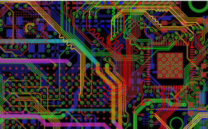
When it comes to high speed traces, a designer needs to know the rules for essential routing, including not cutting ground planes and keeping trails short. So prevent digital lines a certain distance from crosstalk, and shield any interference creating elements so that damaging the signal integrity.
3. Routing traces with impedance control
It needs impedance matching for some types of signals which are about 40-120 ohms. And characteristic impedance matched hints are antennae and many differential pairs.
It’s important for designer to know how to calculate trace width and layer stack for necessary impedance values. If there is not correct impedance values, it may make a serious effect on signal, which will lead to data corruption.
4. Length matching traces
There are many lines in high speed memory buses and interface buses. The lines can work at quite high frequency, so it’s vital that the signals need to be from the transmitting terminal to the receiving terminal at the same time. What’s more, it needs to a feature called length matching. So most common standards define tolerance values that need to match length.
How to know if you need a high speed design?
1. It there high speed interface in your board?
A fast method to find out if you need to abide by high speed design guidelines is to check whether you have high speed interfaces, for example DDR, PCI-e, or even video interfaces like DVI, HDMI and so on.
There are some high speed design rules you need to follow for all these interfaces. What’s more, offer the accurate specifications of each data in the documentation.
2. The ratio of your trace length to the wavelength of signals
In general, your PCB will certainly need a high speed design if the wavelength of your message is the same as the trace length. Because some standards such as DDR require traces that have a length matched to minimal tolerances.
A great rough figure is that if your trace length and wavelength can control within one order of each other. Then you’d better check the high speed designs.
3. PCB with wireless interfaces
As you know, each PCB has an antenna, it needs to design for high speed signals no matter what through the connector or on the board. What’s more, onboard antennas also require close impedance to match tune length.
It will need to connect to the connectors that have a specific impedance value for circuit boards with SMA connectors or similar.
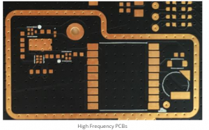
Want High Frequency PCB Price and Get PCB materials recommend,Send mail to kell@ymspcb.com.
Learn more about YMS products
Post time: Mar-04-2022