
High Frequency Printed Circuit Board

What is High Frequency(HF) PCB?
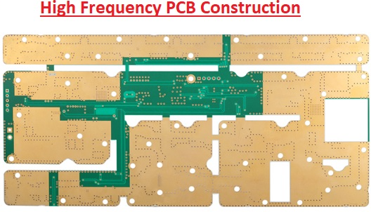
High frequency PCB board refers to the special electromagnetic frequency circuit board, used in high frequency (greater than 300 MHZ frequency or wavelength is less than 1 meter) and microwave (greater than 3 GHZ frequency or wavelength is less than 0.1 meters) in the field of PCB, is on the microwave base copper clad using common rigid circuit board manufacturing method of a part of the process or the use of special processing methods and the production of circuit boards.Electronic devices with high frequency are the developing tendency nowadays, especially in the wireless networks. Satellite communication growing rapidly, information products move towards high speed and high frequency. Thus developing new products always need to use high frequency substrate, satellite system, mobile telephone receiving base station and so on, these communication products must use high frequency PCB.
The features of high frequency PCB

1. DK should be small and stable enough, usually the smaller the better, high DK may lead to signal transmission delay.
2. DF should be small, which mainly affect the quality of signal transmission, the smaller DF could make smaller signal wastage accordingly.
3. The thermal expansivity should be the same with copper foil as much as possible because the difference will lead to copper foil separated in the changes of cold and heat.
4. Water absorptivity must be low, high water absorptivity will affect DK and DF when in a wet environment.
5. Heat-resisting property, chemistry resisting, impact endurance, peel off resisting must be good.
Materials used for HF circuit board.

High frequency board for wireless applications and data rates in the upper GHz range have special demands on the material used:
1. Adapted permittivity.
2.Low attenuation for efficient signal transmission.
3.Homogeneous construction with low tolerances in insulation thickness and dielectric constant.
Generally speaking, high frequency can be defined as frequency above 1GHz. Currently, PTFE material is widely used in high frequency PCB manufacturing, it's also called Teflon, which frequency is normally above 5GHz. Besides, FR4 or PPO substrate can be used to the product frequency among 1GHz~10GHz. These three high frequency substrates have below differences:
Concerning the laminate cost of FR4, PPO and Teflon, FR4 is the cheapest one, while Teflon is the most expensive one. In terms of DK, DF, water absorption and frequency feature, Teflon is the best. When product applications require frequency above 10GHz, only can we choose Teflon PCB substrate to manufacture. The performance of Teflon is far better than other substrates, However, the Teflon substrate has the disadvantage of high cost and large heat-resisting property. To improve PTFE stiffness and heat-resisting property function, a large number of SiO2 or fiber glass as the filling material. On the other hand, due to molecule inertia of PTFE material, which it is not easy to combine with copper foil, thus, it needs to do the special surface treatment on the combination side. Concerning combination surface treatment, normally use chemical etching on PTFE surface or plasma etching to plus surface roughness or add one adhesive film between PTFE and copper foil, but these may influence dielectric performance.
What is RF PCB?
Radio frequency printed circuit boards (RF PCBs) are an exciting, fast growing sector of the PCB manufacturing industry. ... The engineers at YMS can assist you with every step of the fabrication and assembly process, including material selection and key RF PCB manufacturing challenges to be aware of.
How do you make high frequency PCB?
High Frequency PCB Layout Techniques
The less alternating leads of the pins between the layers of high frequency circuits, the better. ...
The shorter the lead between the pins of high-frequency circuits is, the better it is. ...
The less bend between the pins of high-frequency electronic devices, the better.
Products categories
-
Thick Copper PCB 10 Layer (4OZ) High Tg Full B...
-
10 Layer High Tg Hard Gold HDI Board | YMS PCB
-
10 Layer High Tg Immersion gold Boad | YMS PCB
-
China PCB 6Layer Gold Finger Blue Soldermask Bo...
-
HDI Printed Circuit Board 8Layer 2 Step HDI PCB...
-
Wholesale hard gold PCB multilayer Fr4 high TG ...
-
Rigid flexible pcb 6L HDI PCB Laser via copper ...
-
Metal core PCB embedded copper coin pcb High fr...


