
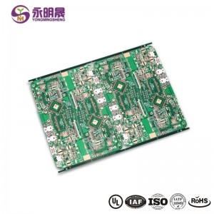
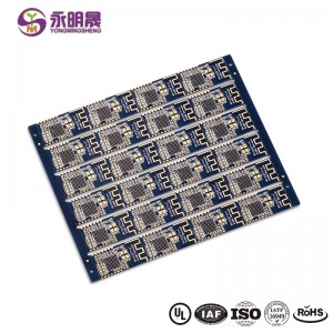
HDI printed circuit boards 8Layer 2 Step HDI Board| YMS PCB

PCB HDI is the high-density interconnector PCB. It is a type of PCB technology that is very popular in various devices. HDI PCBs are the results of miniaturization of components and semiconductor packages because they can realize more functions on the same or less board area through some technologies.
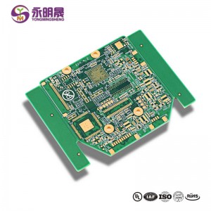
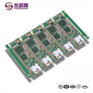
HDI PCBs have finer lines, minor holes, and higher density than conventional PCBs, providing necessary touting solutions for the chips with many pins in mobile devices and other high-tech products.HDI PCB usually has 4,6,8 layer or even higher.
HDI design combines dense component placement and finer circuits, using less board without compromise functions. Compared to ordinary PCBs, the main difference is that HDI PCBs realize the interconnect through blind vias and buried vias instead of through holes. And HDI PCBs use laser drilling while traditional PCBs usually use mechanical drilling. The birth of the HDI PCBs brings more possibilities for portable electronic devices and more challenges for PCB manufacturers. For accommodating the trend of miniaturization and multifunction of electronics, YMS has done a lot to improve the level of equipment and staff professionalism. You can be assured to offer us the HDI designs, and we will give you a satisfactory service and HDI products.
processus de production Conseil IDH:
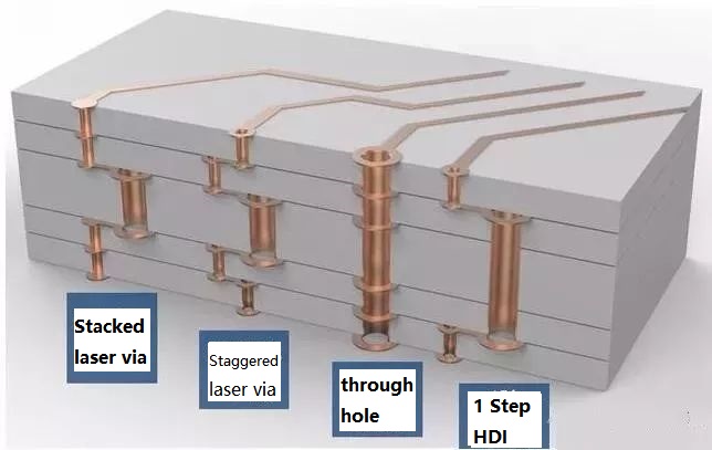
At present, HDI board interconnection between layer and layer is mainly the following design: Staggered holes interconnection, Cross-layer interconnection, ladder interconnection and superposition holes interconnection. Among them, the superposition holes interconnection occupy the least space. There is a research suggests that reducing the number of through holes and increasing the number of blind holes can effectively improve the wiring density. And in the superposition interconnection, the methods of electroplating and resin plug are mainly used, especially the electroplating hole filling method which has more obvious advantages like high reliability and good conduction performance. Therefore, superposition interconnection is the most widely used design method for blind holes design. The process of stacking between layers is as follows: first blind hole is made, then second blind hole is made after lamination, then multi-blind hole is made according to this method, and the interconnection between layers is realized by electroplating hole filling method.
Dans l'ensemble, le processus de production de la plaque HDI est complexe, qui doit être achevé après plusieurs périodes de production pendant une longue période. Il est non seulement des exigences élevées pour le contrôle de la précision et le retrait de chaque couche, mais aussi des normes élevées dans les matériaux, l'équipement, l'environnement et le personnel technique.
YMS HDI PCB manufacturing capabilities:
| Présentation des capacités de fabrication de circuits imprimés YMS HDI | |
| Fonctionnalité | capacités |
| Nombre de couches | 4-60L |
| Technologie PCB HDI disponible | 1 + N + 1 |
| 2 + N + 2 | |
| 3 + N + 3 | |
| 4 + N + 4 | |
| 5 + N + 5 | |
| N'importe quelle couche | |
| Épaisseur | 0,3 mm à 6 mm |
| Largeur et espace minimum de la ligne | 0,05 mm / 0,05 mm (2 mil / 2 mil) |
| PITCH BGA | 0,35 mm |
| Taille minimum percée au laser | 0,075 mm (3 nil) |
| Taille percée mécanique minimale | 0,15 mm (6 mil) |
| Rapport hauteur / largeur pour trou laser | 0,9: 1 |
| Rapport hauteur / largeur pour trou traversant | 16: 1 |
| Finition de surface | HASL, HASL sans plomb, ENIG, étain d'immersion, OSP, argent d'immersion, doigt d'or, galvanoplastie d'or dur, OSP sélectif , ENEPIG.etc. |
| Via l'option de remplissage | Le via est plaqué et rempli d'époxy conducteur ou non conducteur, puis recouvert et plaqué |
| Rempli de cuivre, rempli d'argent | |
| Laser via fermeture plaquée cuivre | |
| enregistrement | ± 4 mil |
| Masque de soudure | Vert, rouge, jaune, bleu, blanc, noir, violet, noir mat, vert mat, etc. |
En savoir plus sur les produits YMS
Lire plus d'actualités

What is HDI material?
FR4 Fiberglass board or ceramic board
Are printed circuit boards still used?
Yes,the Printed circuit board(PCB) is the foundation of electronic equipment, and it can be found in every electronic device in today ’s world
What is the major disadvantage of printed circuit boards?
1.single use 2.environmental pollution 3.high cost
Is there gold in printed circuit boards?
yes,there is
Catégories de produits
-
Wholesale Multi Layer PCB-PCB Manufacturer Chin...
-
Carte de circuit imprimé HDI 8 couches 2 étapes HDI PCB ...
-
Écran d'affichage LED pcb HDI laser via dans PAD cop ...
-
Toute couche hdi pcb 12 couches décalées Vias immers ...
-
HDI pcb 3 + N + 3 Laser via fermeture cuivrée Coulé ...
-
Micro via PCB HDI PCB 8L 1 + N + 1 Via sur PAD | YMSPCB


