
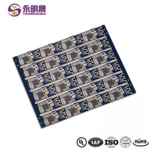
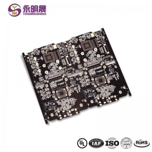
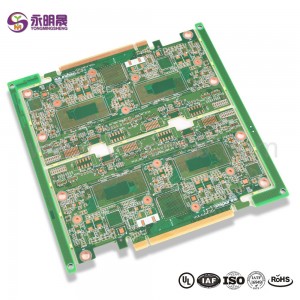
HDI printed circuit boards 8Layer 2 Step HDI Board| YMS PCB

PCB HDI is the high-density interconnector PCB. It is a type of PCB technology that is very popular in various devices. HDI PCBs are the results of miniaturization of components and semiconductor packages because they can realize more functions on the same or less board area through some technologies.
HDI PCBs have finer lines, minor holes, and higher density than conventional PCBs, providing necessary touting solutions for the chips with many pins in mobile devices and other high-tech products.HDI PCB usually has 4,6,8 layer or even higher.
HDI design combines dense component placement and finer circuits, using less board without compromise functions. Compared to ordinary PCBs, the main difference is that HDI PCBs realize the interconnect through blind vias and buried vias instead of through holes. And HDI PCBs use laser drilling while traditional PCBs usually use mechanical drilling. The birth of the HDI PCBs brings more possibilities for portable electronic devices and more challenges for PCB manufacturers. For accommodating the trend of miniaturization and multifunction of electronics, YMS has done a lot to improve the level of equipment and staff professionalism. You can be assured to offer us the HDI designs, and we will give you a satisfactory service and HDI products.
HDI Board proceso de produción:
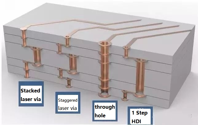
At present, HDI board interconnection between layer and layer is mainly the following design: Staggered holes interconnection, Cross-layer interconnection, ladder interconnection and superposition holes interconnection. Among them, the superposition holes interconnection occupy the least space. There is a research suggests that reducing the number of through holes and increasing the number of blind holes can effectively improve the wiring density. And in the superposition interconnection, the methods of electroplating and resin plug are mainly used, especially the electroplating hole filling method which has more obvious advantages like high reliability and good conduction performance. Therefore, superposition interconnection is the most widely used design method for blind holes design. The process of stacking between layers is as follows: first blind hole is made, then second blind hole is made after lamination, then multi-blind hole is made according to this method, and the interconnection between layers is realized by electroplating hole filling method.
En xeral, o proceso de produción da tarxeta HDI é complexa, que ten que ser rematada despois de moitas veces de produción por un longo tempo. Non é só altas esixencias de precisión e encollemento de control de cada capa, pero tamén altos estándares de materiais, equipos, ambiente e persoal técnico.
YMS HDI PCB manufacturing capabilities:
| Descrición xeral das capacidades de fabricación de PCB YMS HDI | |
| Función | capacidades |
| Reconto de capas | 4-60L |
| Tecnoloxía de PCB HDI dispoñible | 1 + N + 1 |
| 2 + N + 2 | |
| 3 + N + 3 | |
| 4 + N + 4 | |
| 5 + N + 5 | |
| Calquera capa | |
| Espesor | 0,3 mm-6 mm |
| Ancho e espazo mínimo da liña | 0.05mm / 0.05mm (2mil / 2mil) |
| BGA PITCH | 0,35 mm |
| Tamaño mínimo perforado con láser | 0,075 mm (3 nil) |
| Tamaño mínimo perforado mecánico | 0,15 mm (6 millas) |
| Relación de aspecto para burato láser | 0,9: 1 |
| Relación de aspecto para o burato pasante | 16: 1 |
| Acabado superficial | HASL, HASL sen chumbo, ENIG, estaño de inmersión, OSP, prata de inmersión, dedo de ouro, ouro duro galvanizado, OSP selectivo , ENEPIG.etc. |
| Opción de recheo vía | A vía está chapada e chea de epoxi condutora ou non condutora e logo tapada e recuberta |
| Enchido de cobre, cheo de prata | |
| Láser mediante peche de cobre | |
| Rexistro | ± 4mil |
| Máscara de soldar | Verde, vermello, amarelo, azul, branco, negro, roxo, negro mate, verde mate.etc. |
Máis información sobre os produtos YMS

What is HDI material?
FR4 Fiberglass board or ceramic board
Are printed circuit boards still used?
Yes,the Printed circuit board(PCB) is the foundation of electronic equipment, and it can be found in every electronic device in today ’s world
What is the major disadvantage of printed circuit boards?
1.single use 2.environmental pollution 3.high cost
Is there gold in printed circuit boards?
yes,there is
categorías produtos
-
Láser HDI 3 + N + 3 láser mediante fundición de cobre bañado en cobre ...
-
Circuíto impreso HDI 8Layer 2 Step HDI PCB ...
-
Wholesale Multi Layer PCB-PCB Manufacturer Chin...
-
HDI PCB 12 Layer 2 Step HDI Board | PCB YMS
-
HDI PCB 2 + n + 2 VIPPO High Density Interconnect P ...
-
Inserción de alta velocidade de PCB HDI de calquera capa ...


