
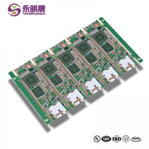
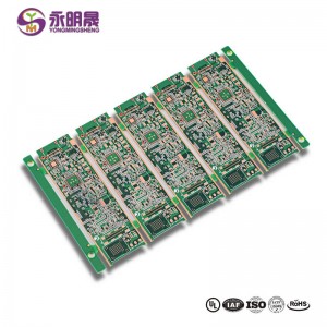
HDI printed circuit boards 8Layer 2 Step HDI Board| YMS PCB

PCB HDI is the high-density interconnector PCB. It is a type of PCB technology that is very popular in various devices. HDI PCBs are the results of miniaturization of components and semiconductor packages because they can realize more functions on the same or less board area through some technologies.
HDI PCBs have finer lines, minor holes, and higher density than conventional PCBs, providing necessary touting solutions for the chips with many pins in mobile devices and other high-tech products.HDI PCB usually has 4,6,8 layer or even higher.
HDI design combines dense component placement and finer circuits, using less board without compromise functions. Compared to ordinary PCBs, the main difference is that HDI PCBs realize the interconnect through blind vias and buried vias instead of through holes. And HDI PCBs use laser drilling while traditional PCBs usually use mechanical drilling. The birth of the HDI PCBs brings more possibilities for portable electronic devices and more challenges for PCB manufacturers. For accommodating the trend of miniaturization and multifunction of electronics, YMS has done a lot to improve the level of equipment and staff professionalism. You can be assured to offer us the HDI designs, and we will give you a satisfactory service and HDI products.
HDI Consiglio processo di produzione:
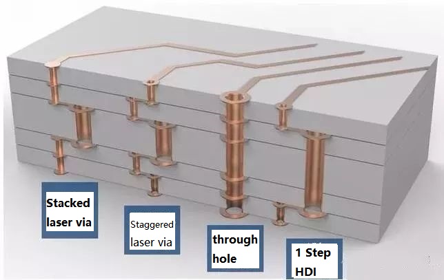
At present, HDI board interconnection between layer and layer is mainly the following design: Staggered holes interconnection, Cross-layer interconnection, ladder interconnection and superposition holes interconnection. Among them, the superposition holes interconnection occupy the least space. There is a research suggests that reducing the number of through holes and increasing the number of blind holes can effectively improve the wiring density. And in the superposition interconnection, the methods of electroplating and resin plug are mainly used, especially the electroplating hole filling method which has more obvious advantages like high reliability and good conduction performance. Therefore, superposition interconnection is the most widely used design method for blind holes design. The process of stacking between layers is as follows: first blind hole is made, then second blind hole is made after lamination, then multi-blind hole is made according to this method, and the interconnection between layers is realized by electroplating hole filling method.
Nel complesso, il processo di produzione del piatto HDI è complessa, che deve essere completata dopo molte volte di produzione per un lungo tempo. È non solo elevati requisiti per la precisione e restringimento controllo di ogni strato, ma anche elevati standard di materiali, attrezzature, ambiente e personale tecnico.
YMS HDI PCB manufacturing capabilities:
| Panoramica delle capacità di produzione di PCB YMS HDI | |
| Caratteristica | capacità |
| Conteggio strati | 4-60L |
| Tecnologia PCB HDI disponibile | 1 + N + 1 |
| 2 + N + 2 | |
| 3 + N + 3 | |
| 4 + N + 4 | |
| 5 + N + 5 | |
| Qualsiasi strato | |
| Spessore | 0,3 mm-6 mm |
| Larghezza e spazio minimo della linea | 0,05 mm / 0,05 mm (2mil / 2mil) |
| PASSO BGA | 0,35 mm |
| Dimensione min forata laser | 0,075 mm (3 a zero) |
| Dimensione minima forata meccanica | 0,15 mm (6 mil) |
| Proporzioni per foro laser | 0.9: 1 |
| Rapporto d'aspetto per foro passante | 16: 1 |
| Finitura superficiale | HASL, HASL senza piombo, ENIG, Immersion Tin, OSP, Immersion Silver, Gold Finger, Galvanotecnica Hard Gold, OSP selettivo , ENEPIG.etc. |
| Tramite l'opzione di riempimento | Il via è placcato e riempito con resina epossidica conduttiva o non conduttiva, quindi ricoperto e placcato |
| Riempito di rame, riempito d'argento | |
| Laser via rame placcato chiuso | |
| Registrazione | ± 4mil |
| Maschera per saldatura | Verde, rosso, giallo, blu, bianco, nero, viola, nero opaco, green.etc opaco. |
Scopri di più sui prodotti YMS
Leggi altre notizie

What is HDI material?
FR4 Fiberglass board or ceramic board
Are printed circuit boards still used?
Yes,the Printed circuit board(PCB) is the foundation of electronic equipment, and it can be found in every electronic device in today ’s world
What is the major disadvantage of printed circuit boards?
1.single use 2.environmental pollution 3.high cost
Is there gold in printed circuit boards?
yes,there is
categorie di prodotti
-
LED SMD schermo di visualizzazione pcb Micro led pcb mini l ...
-
Circuito stampato HDI 8Layer 2 Step HDI PCB ...
-
PCB HDI 3 + N + 3 Laser tramite otturatore ramato Cast ...
-
HDI pcb any layer hdi pcb ad alta velocità di inserimento ...
-
Any layer hdi pcb 12Layer Staggered Vias Immers ...
-
Scheda HDI HDI a 12 strati e 2 fasi | YMS PCB


